
Khani Solutions · Independent cryogenic CFD study
Propellant in motion.
From ground fill to lunar restart.
Ground filling, engine cutoff, slosh, settling and restart: native 2D OpenFOAM liquid fields inside transparent 3D CAD, with fixed-scale plots and a schematic mission map.
By Mohammadreza Khani, PhD · Public references and assumed inputs · Not Blue Origin hardware, a Blue Moon MK2 reconstruction or employer project results.
108 seconds · Silent · 1080 × 1350. Short analysis windows and coast intervals are compressed for presentation.
The engineering question
Liquid location matters as much as liquid inventory. A tank may contain ample propellant while its feed region contains gas after engine cutoff or a maneuver. This independent study explores how a prescribed acceleration history changes the liquid interface, how long settling takes, and what happens during engine startup. It connects CAD, a deliberately inexpensive multiphase calculation, a separate pressurant inventory model and a mission storyboard.
The goal is a fast, inspectable portfolio demonstration of the analysis workflow. The film shows computed liquid motion; the detailed hardware and mission assemblies provide context. It does not establish a flight-ready tank, liquid acquisition device or restart sequence.
How the geometry and visualization were built
The editable Blender assembly contains 35 tank CAD components, including the shell and domes, baffles, liquid acquisition hardware, a pressurant diffuser and feed tube, a separate vent, plumbing and insulation display geometry. Public references informed the concept; internal dimensions, component placement and operating inputs are study assumptions. The earlier Falcon 9-inspired CAD foundation and this generic lunar tank demonstration are independent models, rather than a reconstruction of Blue Origin hardware.
For speed, the numerical domain is a planar, one-cell-thick mesh with 2,118 cells. It resolves the bulk liquid and three pairs of zero-thickness baffles. The detailed LAD screens/channels, diffuser holes, feed tubes and MLI are CAD display geometry. Their pores, pressure loss, jets and thermal performance are not resolved.
Postprocessing interpolates saved native VOF values to points and clips the liquid at a volume fraction of 0.5. A thin planar liquid slab sits inside the transparent 3D tank. Display interpolation smooths playback between saved states; it does not convert the calculation into 3D CFD. Four fixed-axis histories show liquid inventory, the separate 0D ullage estimate, outlet liquid fraction and axial load.
Following the tank through the mission
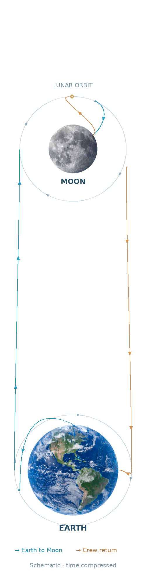
The 35 windows cover ground fill, launch, cutoff/coast, settling and pressurization, Earth departure, translunar coast, capture, orbital refill, descent, landing, a shortened surface hold, lunar liftoff, transfer, insertion, rendezvous and docking. The sidebar then follows the crew vehicle through Earth departure, return, service-module separation, entry, parachutes and splashdown.
The LOX tank stays with the lander in lunar orbit after crew transfer. It is not an Orion tank and its remaining LOX is not consumed for the crew vehicle’s return. Blue and orange routes distinguish outbound travel and return. Moving assembly icons show staging, refill and docking changes. These are schematic paths with smooth tangent joins, compressed time and changing display scale; they are not a propagated Earth–Moon flight solution.
The mission architecture is generic. A dated NASA public HLS architecture and NASA/ESA Orion material informed the handoff between lander and crew vehicle. A separately calculated point-mass ascent and a public NASA/JPL periodic-orbit reference support the numerical study; the final simplified map is an explanatory drawing, not that reference orbit or an operational ephemeris.
Numerical method and model boundaries
Native OpenFOAM 2512 interFoam, with a custom mission driver, computes incompressible, isothermal, laminar VOF flow with surface tension, constant-density gas and an assumed 15° wetting wall condition. Equivalent volume scaling tracks a full-tank inventory without adding a third spatial dimension. AI assistance supported research, CAD/setup automation, scripting and postprocessing; OpenFOAM performed the numerical flow solution.
In the tank frame, prescribed thrust acceleration acts opposite the applied main-engine or axial RCS force divided by the modeled vehicle mass. Freely falling coasts use zero uniform apparent gravity. A supported tank on the Moon uses 1.62 m/s². Lunar gravity is therefore not incorrectly used as a uniform settling force in orbit. The continued ascent windows also include prescribed planar Coriolis, Euler and centrifugal terms from the imposed attitude program. Vehicle rotation and guidance are not solved as a coupled six-degree-of-freedom problem.
The assumed propulsion inputs are 180 kN main thrust, 440 s specific impulse, oxygen/fuel mass ratio 6, 8,000 kg fixed hardware, and a 500 kg initial RCS reserve at 220 s specific impulse. Nominal axial settling uses 1,000 N divided by the changing modeled mass; rendezvous uses smaller prescribed 100 N pulses. LOX withdrawal follows thrust and specific impulse, with 1,141 kg/m³ liquid density. A companion-fuel mass proxy is budgeted; no LH₂ flow calculation is performed. These values are generic study inputs, not published vehicle specifications.
The ullage plot is a separate, one-way isothermal ideal-helium inventory estimate at 110 K with assumed 250/300 kPa control targets. It is not compressible ullage CFD or gas-jet forcing. There is no chilldown, heat leak, boiloff, evaporation/condensation, active refrigeration, thermal collapse-factor prediction or TPS qualification. Surface stays and coasts are shortened analysis windows, not a multi-day storage simulation.
Results and the restart revision
| Measure | Result | Interpretation |
|---|---|---|
| Completed sequence | 35 windows; 3,022 native snapshots | Execution and saved-state coverage, not scientific validation |
| Ground fill / orbital refill | 95.010% / 70.001% | Assumed inventory schedule; ullage remains |
| Landing / final LOX inventory | About 31.3% / 9.711% | Inventory carried through the sequence without a surface refill |
| Maximum inventory balance error | 2.29 × 10⁻⁶% of tank | Bookkeeping check; not a spatial-accuracy estimate |
| Raw liquid fraction extrema | −3.52 × 10⁻¹⁶ to 1.000000219 | Small numerical excursions retained in the review |
| Minimum outlet liquid fraction during revised insertion burn | 98.05% (previously 95.94%) | Improved acquisition indicator; residual modeled gas remains |
| Remaining axial RCS budget | 7.51 kg | Only this prescribed program; not a complete attitude-control budget |
The first continuation exposed a useful failure: a fixed 45 s settling interval ended with only about 93.9% liquid at the modeled outlet. The revised restart waits for outlet liquid fraction above 99.5% continuously for 2 s, then applies a 10 s smoothstep main-engine ramp with overlapping axial RCS. Settling extended to 55.2 s. Minimum liquid fraction during the insertion burn improved from 95.94% to 98.05%.
That improvement does not demonstrate gas-free delivery. A coarse outlet-cell fraction cannot qualify LAD performance, cavitation margin or engine restart reliability. The remaining modeled gas is an unresolved design concern, and the film retains it rather than presenting a clean restart.
The continuation used adaptive stepping with a 0.02 s cap, target Courant number 0.35 and interface Courant target 0.20. The recorded original peak Courant number was 0.945; the new continuation peak was 0.451. All windows completed, but no grid/time-step independence study or experimental validation was performed. A separate ascent replay using actual starting mass reached about 100.012 km altitude and 1,633.61 m/s tangential speed versus a local circular value of 1,633.50 m/s; this checks the prescribed point-mass program, not the VOF model or a flight guidance system.
What I would test next
The next engineering step would be to separate the screening questions: refine interface and baffle sensitivity; resolve or calibrate LAD screen resistance and gas ingestion; model diffuser jets and local thermal mixing; couple compressible ullage mass/energy with wall heat transfer and phase change; and compare against published experiments before drawing design conclusions. The present model demonstrates the workflow and its diagnostics while keeping those unperformed analyses explicit.
Inspect the study
Public reference material
Blue Origin: Blue Moon overview provides public program context, not this tank’s geometry or operating inputs. NASA OIG IG-26-004, March 10, 2026 is the dated HLS architecture reference. NASA’s Orion reference and ESA’s service-module propulsion description support the separate crew-return context. NASA/JPL’s periodic-orbits API supplies the study’s reference-orbit framework, not an operational Gateway or Blue Moon ephemeris.