What the 0°–20° study shows
I extended the public-reference exterior reconstruction to eleven independent, unpowered calculations: 0°, 2°, 4°, 6°, 8°, 10°, 12°, 14°, 16°, 18° and 20° angle of attack at 100 mph. The stationary aircraft and camera make the changing inflow direction, surface loading and near-aircraft flow paths easier to compare. The native velocity and surface-traction fields come from OpenFOAM, while the three-second 0° → 20° → 0° sequence is an edited presentation of those fields.
The useful question is how increasing incidence changes the modeled lift/drag tradeoff and where the computed flow bends or reverses. The screening curve shows diminishing lift gains at higher angles and a strong drag increase. It identifies regions and angles for a better-resolved follow-up; it does not establish a production-aircraft performance curve, a stall angle, or a safe flight envelope.
This is an independent Khani Solutions demonstration built from public Archer Midnight photographs, exterior views and patent illustrations. It appears alongside the Wisk methods demos because it illustrates related engineering tools. Archer Midnight and Wisk’s aircraft are different designs. No employer or manufacturer geometry, operating data, proprietary battery details or flight-test results were used.
Surface colors: local signed lift or drag per unit area
The selectable colored variable is aerodynamic force contribution per surface area, in N/m² (equivalently Pa). It includes pressure and modeled viscous shear. It is neither surface pressure coefficient Cp, integrated lift/drag coefficient CL/CD, nor structural stress. A force density can have either sign: one patch can assist the selected load while another opposes it.
The incompressible OpenFOAM pressure is kinematic pressure pkin, in m²/s². With density ρ, outward normal of the fluid boundary nfluid, and OpenFOAM’s kinematic wall-shear vector τOF, the body traction used here is t = ρ pkin nfluid − ρ τOF. The installed OpenFOAM force and wall-shear conventions were checked before integration. The surface uses a zero-gauge reference; local pressure contributions depend on that reference, while a consistent closed-body pressure integral eliminates a uniform pressure offset.
Body X points from nose toward tail, Y spans the aircraft and Z points upward. At angle α, U∞ = V(cos α, 0, sin α), drag direction eD = (cos α, 0, sin α), and lift direction eL = (−sin α, 0, cos α). Colors show t·eL or t·eD. Native surface-cell tractions and areas are retained; cell-to-vertex averaging is used only for a smoother display. The common clipping ranges, ±1,800 Pa for lift and ±1,000 Pa for drag, allow comparison across angles. Saturated colors hide excursions beyond those display limits rather than limiting the calculated load.
The green lift and amber drag arrows share one length scale across all cases. They represent integrated wind-axis forces, with an illustrative drawing anchor. Their origin is not a calculated center of pressure or known aircraft center of gravity. The right-side plots contain all eleven case means; the highlighted point and vertical band track the displayed case. Whiskers show the minimum and maximum force within the declared iteration window, not confidence intervals or physical-time fluctuations.
Streamlines: calculated paths with presentation arrowheads
Cyan lines are selected paths through the native velocity field around the fuselage, above/below the wing and near the tail. Purple lines are selected near-body reverse-flow segments where the current solver iterate supports them. Curvature shows the calculated deflection of the flow. These lines are not a uniform sampling of the flow, and their count, spacing, brightness and thickness do not represent mass flow or boundary-layer thickness. A curling streamline in an unconverged steady field is a recirculation candidate, not proof of a resolved coherent vortex or a vortex-shedding frequency.
The body-fixed seed set used 90 wing releases distributed over 15 spanwise locations and six vertical offsets, 40 cabin releases at five lateral positions and eight heights, and eight tail releases. Each case could add up to 40 spatially separated seeds in near-body cells with reversed wind-axis velocity. Thus the main release positions are comparable across angles, while the wake seeds are selected from each case’s computed field.
PyVista/VTK traced paths bidirectionally using native U, an initial step of 0.025 m, minimum/maximum steps of 0.002/0.07 m, up to 3,000 steps, maximum length 16 m, terminal speed 0.15 m/s and integration-error tolerance 10⁻⁶. Cropping, minimum path length, velocity-deflection and spacing filters removed straight bypass paths and reduced overlap. At most five qualifying half-domain reverse-flow candidates were retained before mirroring. Selected full-aircraft path counts vary with angle; the 20° view contains 122 paths. No synthetic vortex curves were inserted.
Arrowheads point along interpolated U and move forward even when the displayed angle returns toward zero. Their speed is illustrative. The return branch reuses the same eleven steady fields; it is not an independently solved descending-angle sequence, a dynamic pitching maneuver, a hysteresis calculation, or three seconds of physical flow evolution. Matching opening/closing source images create the visual loop. The video is 1920 × 1080 at 24 fps; an eleven-second version allows slower inspection.
What the screening curve says
Between 12° and 16°, the mean modeled lift changes little: about 24.28, 24.47 and 24.41 kN, while mean drag rises from about 3.60 to 6.15 kN. At 20°, the mean lift is about 25.63 kN and drag about 8.69 kN. Relative to 12°, that is approximately 5.6% more lift and 142% more drag. The corresponding modeled L/D falls from about 6.75 to 2.95. These ratios describe this untrimmed, approximate, unconverged model; they are not predictions of the real aircraft’s cruise efficiency.
The engineering message is diminishing load benefit with a rapidly increasing drag cost in this particular screening sweep. The highest sampled mean lift occurs at 20°, but the data do not resolve a trustworthy lift maximum or establish a stall threshold. The negative lift at 0° belongs to the assumed symmetric-airfoil draft and its untrimmed orientation, not to an actual Midnight cruise condition.
| AoA | Lift / kN | Drag / kN | CL | CD | Full convergence targets |
|---|---|---|---|---|---|
| 0° | -1.349 | 1.272 | -0.0483 | 0.0455 | Not met |
| 2° | +4.061 | 1.253 | 0.1454 | 0.0449 | Not met |
| 4° | +8.949 | 1.295 | 0.3204 | 0.0464 | Not met |
| 6° | +13.868 | 1.517 | 0.4966 | 0.0543 | Not met |
| 8° | +18.438 | 1.803 | 0.6602 | 0.0646 | Not met |
| 10° | +21.575 | 2.493 | 0.7725 | 0.0893 | Not met |
| 12° | +24.275 | 3.595 | 0.8692 | 0.1287 | Not met |
| 14° | +24.466 | 4.886 | 0.8760 | 0.1750 | Not met |
| 16° | +24.409 | 6.150 | 0.8740 | 0.2202 | Not met |
| 18° | +25.559 | 7.228 | 0.9152 | 0.2588 | Not met |
| 20° | +25.632 | 8.689 | 0.9178 | 0.3111 | Not met |
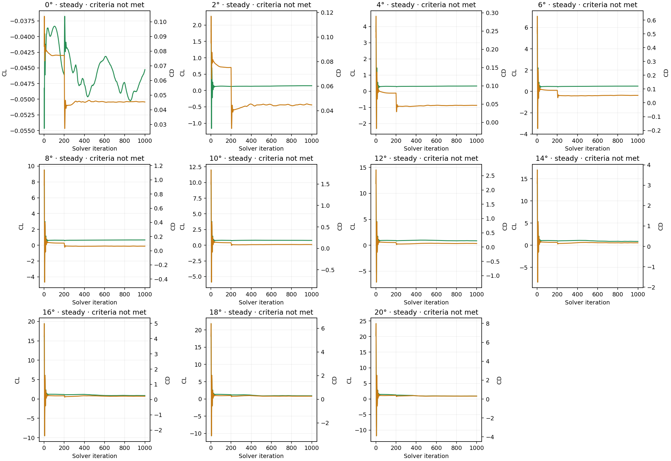
Forces are full-aircraft equivalents: the symmetry-half integral is doubled. Coefficients use the matching half reference area, 11.407946 m²; full reference area is 22.815892 m² from the assumed draft chord distribution. The plots use the last 200 second-order SIMPLE iterations, while colors and streamlines use the final steady iterate. A field integral should therefore be compared with the native final force, not automatically with the iteration-window mean.
What to investigate next
Examine wing/cabin-root transitions, nacelle/boom junctions, exposed gear and the tail in fixed views at the same operating point. Surface traction maps show which patches contribute positively or negatively to a force; velocity paths show where the current field is deflected or reversed. A useful design change still needs a controlled geometry comparison with converged, mesh-sensitive loads. These movies do not demonstrate a fairing benefit or an optimized aircraft.
Priority follow-up is to establish representative airfoil, incidence and twist; improve near-wall resolution and mesh conditioning; resolve the nonlinear force histories; and compare systematically refined grids. High-angle separated flow may require a sufficiently long, time-resolved calculation, timestep sensitivity and statistical averaging. Lift/trim and pitching-moment interpretation require a justified CG and control settings. Rotor interactions require a justified powered representation. Those tasks were not completed by extending the visual angle sweep.
CAD preparation and the high-angle volume mesh
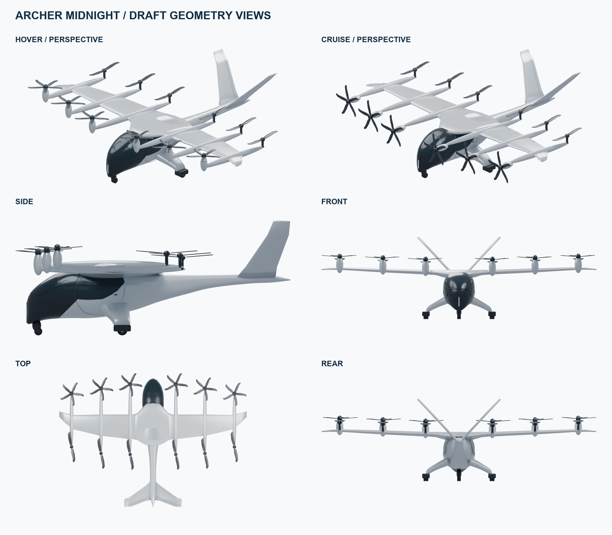
The editable Blender 5.0.1 exterior was reconstructed from multiple public views using a visually fitted fuselage loft, glazing patches, landing-gear fairings, wing-root shoulders, six booms, cruise-oriented forward nacelles/hubs and a V-tail. The main wing uses a generic symmetric 13%-thickness profile; the tail uses a generic 10%-thickness profile. OEM camber, incidence, twist, control settings, trim and structural shape were unavailable. The earlier CAD section below documents scale references and reconstruction assumptions.
The CFD exterior is a separate cleaned body: propeller blades and decorative surface patches were omitted; cabin closure, wings, tail, booms, nacelles/hubs and exposed gear remain. A 25 mm voxel union, smoothing and triangulation produced a connected closed boundary, with approximate component tags. These operations round thin trailing edges and small details. A visually convincing, watertight surface is not evidence of aerodynamic fidelity.
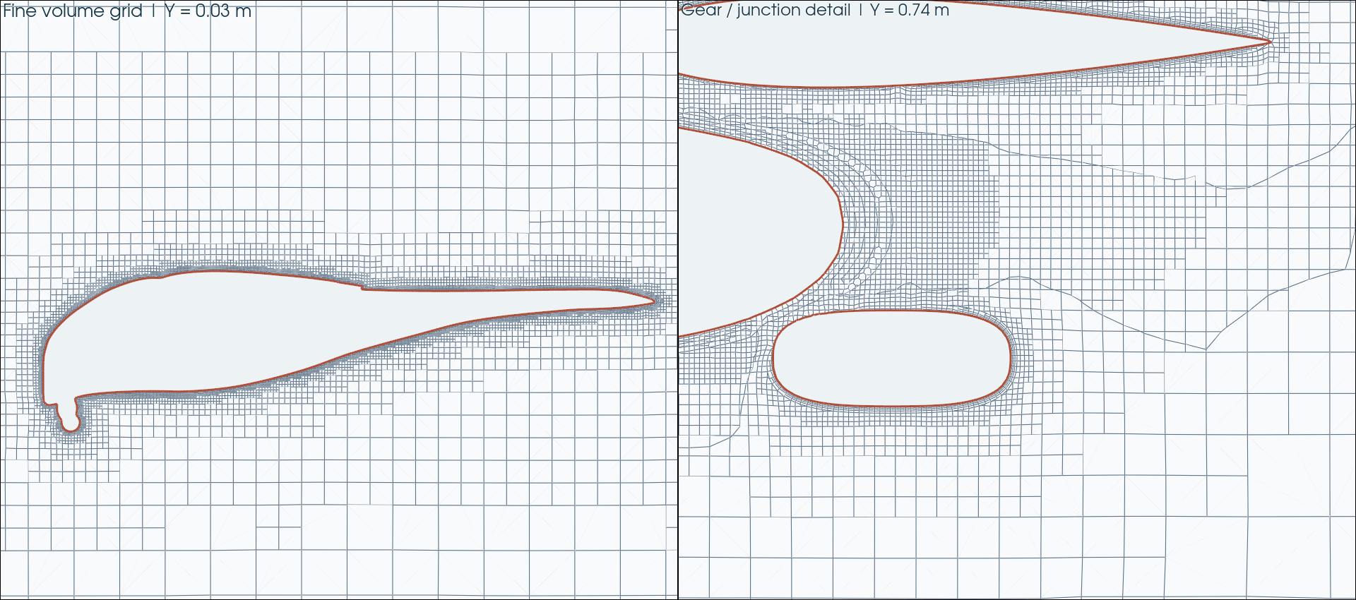
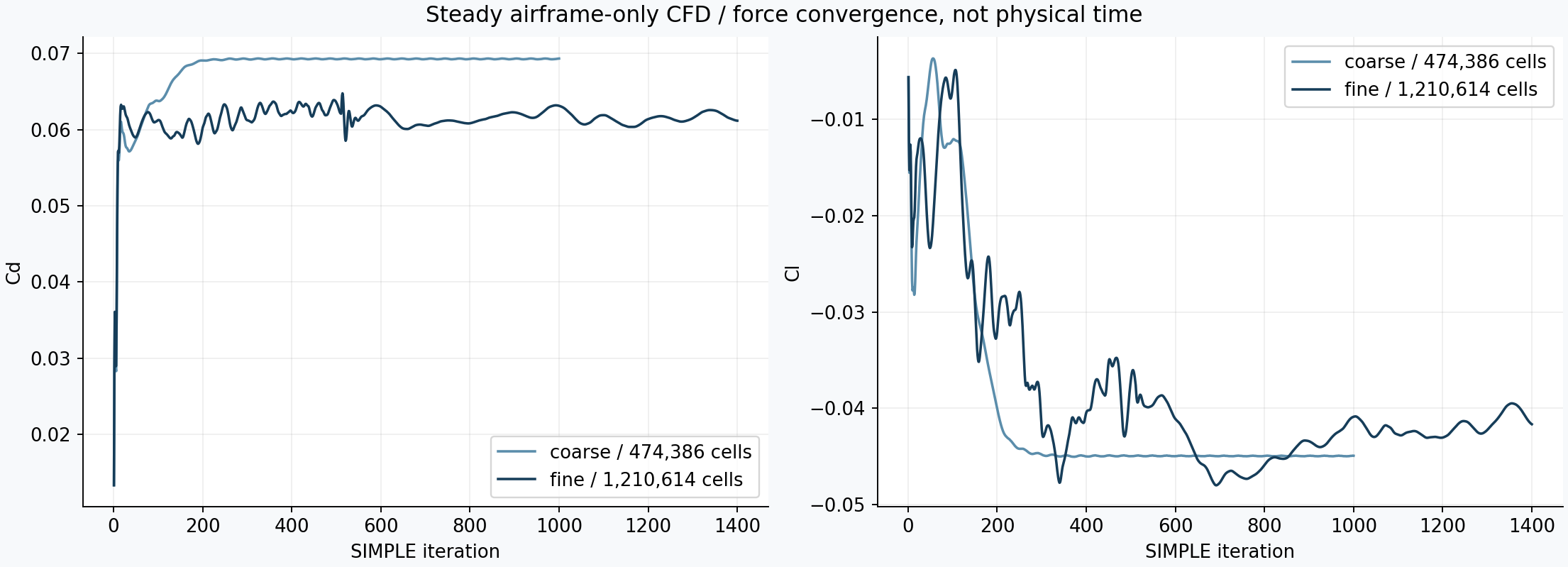
The high-angle study uses a new common 2,226,297-cell symmetry-half mesh for all eleven cases, not the earlier 474,386/1,210,614-cell baseline grids. OpenFOAM v2512 blockMesh and snappyHexMesh refined the wing, tail and nacelle surfaces to level 7 and the other aircraft surfaces to level 6. The near-body box uses level-3 refinement; the refined wake was expanded to X = 0–30 m, Y = 0–10 m and Z = −3–16 m to cover high-incidence flow. The full external half-domain spans X = −35–75 m, Y = 0–35 m and Z = −30–35 m, with symmetry at Y = 0.
Layered meshes and a local cell-splitting repair were tested and rejected because of poor stencil quality. The accepted surface-refined mesh has no extruded prism layers and uses wall-function RANS. This improved the chosen mesh-quality diagnostics but did not establish adequate boundary-layer profiles or skin-friction accuracy. Fifteen tiny deficient fluid cells were closed in three passes (9, 5 and 1); total removed volume has an upper bound of 0.00015 m³. Their new walls were assigned to the nearest existing aircraft patch. The rejected attempts and native audit logs remain in the engineering archive.
Configured mesh checks passed. Expanded audits reported no weak-determinant cells or low-weight faces at the retained criteria; minimum normalized determinant was 0.0011844321 and minimum face weight 0.087647394. The expanded concave-cell diagnostic still failed, identifying 81,478 cells. Thus this is not an “all checks passed” mesh, and it is not grid independent. A mesh fingerprint confirmed that every angle used the same points, faces, ownership, neighbor and boundary files.
Solver settings, execution and acceptance
The computations ran on the Intel Xeon Gold 6238R machine. Meshing used 16 MPI ranks. Each angle used four MPI ranks, with eleven cases scheduled concurrently and an aggregate cap of 44 ranks. The method was OpenFOAM v2512 simpleFoam: steady incompressible RANS with k–ω SST, not a Blender fluid simulation. Blender preserves editable geometry and field attributes; Python, NumPy, PyVista/VTK, Pillow and FFmpeg produced the native-field visualization and H.264 videos.
| Input / numerical choice | High-angle study |
|---|---|
| Speed / density / viscosity | 44.704 m/s (100 mph); 1.225 kg/m³; ν = 1.46 × 10⁻⁵ m²/s |
| Inlet turbulence | 1% intensity, 0.1 m length; k = 0.299767 m²/s², ω = 9.99612 s⁻¹ |
| Dynamic pressure / chord Reynolds number | q∞ ≈ 1,224 Pa; Re ≈ 4.78 × 10⁶ for assumed c = 1.559485 m |
| Initialization | Mapped from the retained 0° screening field; internal velocity rotated and freestream conditions reset for each angle |
| Momentum convection | 200 upwind conditioning iterations; then bounded Gauss limitedLinearV 1 |
| Pressure linear solution | GAMG; absolute tolerance 10⁻⁸, relative tolerance 0.001 |
| U, k and ω linear solution | smoothSolver; absolute tolerance 10⁻⁸, relative tolerance 0.01 |
| Under-relaxation | p = 0.25; U, k and ω = 0.5 |
| Run cap / statistics | 1,000 steady iterations; final 200 second-order iterations for means and ranges |
| Equation-residual targets | Final initial p residual ≤ 10⁻⁴; U, k and ω ≤ 10⁻⁵ |
| Force-window / mass targets | Cd relative peak-to-peak range ≤ 1%; Cl absolute range ≤ 0.002; relative net boundary volume flux ≤ 10⁻⁴ |
Outer boundaries impose the prescribed freestream direction with compatible pressure/freestream treatment; the aircraft is no-slip with zero-gradient pressure and SST wall functions. The archived settings file contains the actual 0° and 20° boundary dictionaries, discretization and SIMPLE controls. At 20°, U∞ ≈ (42.008, 0, 15.2897) m/s, eD = (0.939693, 0, 0.342020), and eL = (−0.342020, 0, 0.939693).
All eleven solves ended normally at their bounded run limit, but none met every declared residual and force-window target. All mass-balance checks passed. Global flux closure and successful process exit do not establish momentum convergence, a stable force curve, a correct separation pattern, or physical validation. SIMPLE “time” in these records is an iteration counter rather than seconds.
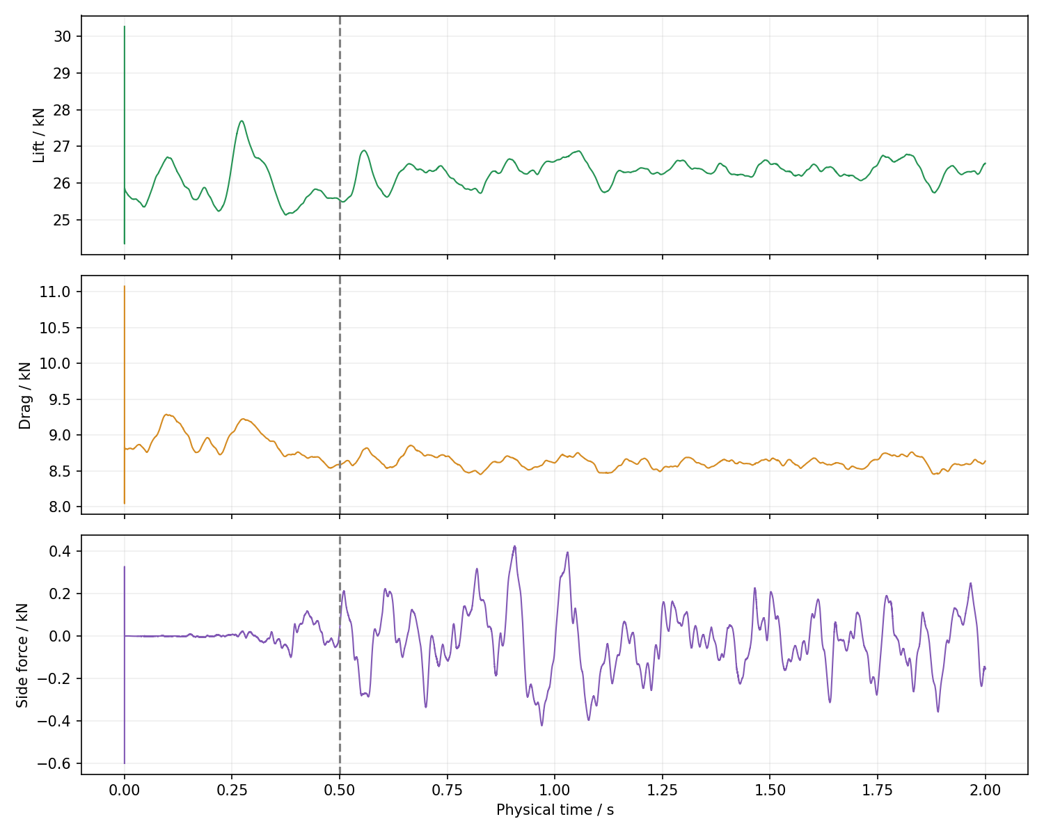
Short pimpleFoam SST URANS trials were initialized from the steady fields, with backward time discretization, two outer corrections, one pressure correction, one non-orthogonal correction, adaptive timestep and maximum Courant number 1. Their measured timestep cost would have required hours to reach useful averaging. They were ended cleanly before the intended 0.03 s averaging start. These short trials produced no usable unsteady mean; every field in the angle-sweep movie is a steady screening iterate. The separate full-domain transient follow-up above subsequently reached approximately 2 s and reports its own statistics and limitations. The short-trial record gives actual termination times and does not treat the video duration as simulated time.
Independent surface pressure/shear integration was cross-checked against native final OpenFOAM forces to verify signs, area mapping and projection. Pressure and viscous integral discrepancies were at most about 0.0362% across the recorded checks. Agreement between two calculations from the same iterate checks post-processing consistency; it does not validate that iterate’s physical accuracy. Coefficient/force normalization and component-force sums were also checked.
Symmetry excludes asymmetric stall modes. No propeller blades, thrust, propwash, resolved rotor wakes, ground effect, internal cooling, trim, structural loads or aeroelastic response were solved. No grid or timestep independence, flight-test correlation, OEM validation, or reliable maximum angle of attack has been established.
Inspect the evidence and editable visualization
The Blender source contains one common stationary mesh, 22 per-vertex scalar attributes (lift and drag for eleven angles), native streamline geometry and wind-axis force arrows. Scene controls CaseIndex = 0…10 and ColorMode = 0/1 select the field and lift/drag coloring. The updated 72-frame timeline sweeps 0° → 20° → 0°. Reopening and every frame’s case/visibility selection were verified on Intel. The final composite movie is rendered with PyVista/VTK; the Blender file is an editable scientific visualization, not a separate CFD solver.
OpenFOAM’s simpleFoam source reference, snappyHexMesh workflow, and force-coefficient normalization explain the methods; the downloaded dictionaries identify this run’s v2512 settings. PyVista’s streamline documentation describes tracing. Public photographs/patents and the full CAD-reference discussion remain in the historical reconstruction section below.
Public portfolio update: October 14, 2026. Numerical values in this steady-sweep section refer to the common-mesh high-angle screening study. Original native volume fields, logs, rejected meshes and execution records remain in the engineering archive.